

Custom electronic
enclosures.
Precision at every interface.
Metal bodies and covers for storage and electronic modules. Built around your board, connector and mating requirements.
Explore the component pair
A small envelope.
Many critical interfaces.
A custom electronic enclosure locates and protects the assembly inside. This thin body and cover show the mechanical questions behind that task: board support, connector access, thermal contact and repeatable closure.
Drag to rotate · Scroll or pinch to zoom
Body and cover from the supplied CAD, shown in their original alignment. Fasteners and electronics are not included. Nominal geometry and display finish do not establish manufacturing tolerances or tested performance.
A storage-scale envelope.
A fit worth investigating.
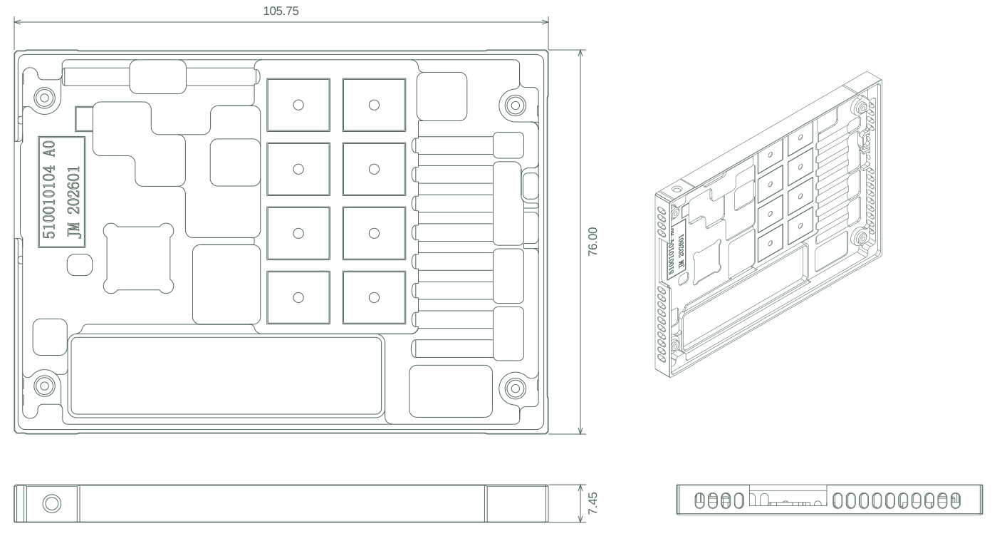
The strongest structural match for this pair is an EDSFF E3.S single-thickness module housing. That is an assessment of the mechanical geometry; the final device and application remain to be confirmed.
For a buyer, the useful comparison is between the bare metal, the connector and the completed module. They have different envelopes.
Related optical module hardware- Body width
- 76 mmMatches the nominal E3.S width.
- Body length
- 105.75 mmCorresponds to 112.75 − 7 mm in the mechanical reference.
- Body thickness
- 7.45 mmA geometric clue for the 7.5 mm device class.
Comparison: SNIA SFF-TA-1008 Rev. 3.0a, Figure 5-3. Selected nominal geometry, not a complete conformance check. The supplied pair excludes the connector and PCB.
What still needs checking
Verify the applicable specification revision, full datum scheme, connector position, carrier, insertion clearances and assembled envelope. Matching selected dimensions does not establish PCIe, NVMe, thermal or electrical compliance.
Denser systems.
More work at the interface.
Enterprise storage is a relevant design direction for precision housings. The opportunity lies in solving a defined mechanical requirement.
The IEA’s 2026 central projection puts global data-centre electricity use at 950 TWh in 2030, up from 485 TWh in 2025, while noting supply-chain bottlenecks. This is infrastructure context, not a forecast of enclosure orders.
SNIA also describes EDSFF formats in the CXL ecosystem. A familiar mechanical outline can therefore serve different electronics. Specify the host interface and thermal conditions before assigning a product category.
For enclosure procurement, the practical response is to review contact surfaces, airflow clearance, service access and revision control together.

Give heat a complete path.
Begin with the heat source, then follow the path through the interface material, the housing and the host cooling system. A pocket or raised land in CAD is a candidate contact feature; its function needs the board layout and thermal stack.
Specify the assembled contact
Identify the contact zone, local flatness and surface texture. Include interface-material thickness, compression limits, fastener sequence and the condition in which the gap is measured. A dimension taken before fastening may not describe the working interface.
Reducing a thermal adhesive’s bondline can lower thermal resistance, but can also affect adhesion. Agree the complete interface and test conditions rather than relying on a material’s conductivity value alone.
Technical context: Power Integrations · Thermal adhesive mounting.
Explore thermal hardwareA finish is part of the interface.
For a custom aluminum enclosure, specify alloy and condition separately from the coating system. Define where appearance matters, where electrical contact is required and which dimensions apply after finishing.
The black rendering follows the supplied product photograph. It does not identify anodizing, painting or any particular coating chemistry.
Close the seam electrically as well as mechanically
Grounding and EMI shielding depend on contact lands, seams, openings, gaskets, fasteners and the specified finish. Include corrosion exposure and the mating materials in the review. Low DC resistance alone does not establish shielding effectiveness.
Technical context: Parker Chomerics · Conductive Elastomer Engineering Handbook.
Review masking and finished fit
Choose the route
around the geometry.
Quantity matters, but so do tool access, thin-wall support and the surfaces that need to stay related. Confirm the route for the actual drawing before comparing piece prices.
Adapt a standard enclosureCutouts, mounting holes and markings
If the main changes are connector cutouts, mounting holes or markings, a modified catalogue enclosure can be a useful benchmark. Check its internal board space and finished interfaces before commissioning a fully custom body.
Machine the internal geometryDrawing-defined lands, pockets and interfaces
Machining from solid is a candidate for development and drawing-defined internal features. Review cutter reach, corner radii, floor thickness, clamping and the order of operations. Agree where local tolerances are necessary instead of applying a tight general tolerance everywhere.
Evaluate a tooled blankGeometry, alloy and repeat quantities
A near-net blank followed by machining may be worth evaluating when geometry, alloy and repeat quantities justify it. Include tooling, draft or parting constraints, finishing, inspection and revision costs in the comparison. The supplied CAD does not identify its original manufacturing process.
Inspect it as it will be assembled.
Metrology and reporting- After machining
- Check drawing datums, critical geometry, burr limits at vents and thread engagement with agreed gauges.
- After finishing
- Verify finished dimensions, local contact faces, cleanliness and the defined cosmetic zones.
- After fastening
- Check the assembled envelope and contact conditions. Retain sample or batch records against the approved drawing revision.
The metal-component scope.
The metalwork.
A clearly defined scope.
XILILAI · Metal components
Body, cover and drawing-defined metal interfaces. Material, manufacturing route, specialist operations, quantities and inspection deliverables are agreed for each project.
System owner · Complete module
Electronics, firmware, mating hardware and complete-module thermal, EMI and reliability requirements. Ceramic components are outside our scope.
Considering industrial control or BMS?
Industrial-control or BMS use needs the actual board, insulation and environmental evidence. This thin module housing should not be presented as a battery-cell enclosure.
Before the first quotation.
Practical answers for your enclosure review.
When is a custom metal enclosure worth considering?
Start with the board and its interfaces. A modified standard enclosure may be sufficient for simple cutouts, mounting holes and markings. Custom internal geometry becomes relevant when board supports, connector positions, contact lands or the available envelope cannot be accommodated by a catalogue product. Compare the complete manufacturing and qualification route before selecting a design.
Is this an E3.S SSD enclosure?
The supplied geometry is strongly consistent with an E3.S single-thickness housing: its width, derived body length and selected side-hole positions align with the SNIA mechanical reference. The final device, connector, mounting hardware and applicable specification revision must be confirmed before claiming E3.S compliance. The enclosure alone does not identify the electronics inside.
Which material and finish should be specified?
The supplied STEP files do not establish the alloy, temper or surface treatment. For a custom aluminum enclosure, specify the alloy and condition, coating system, masking, electrical-contact areas and dimensions after finishing. The black appearance and bright mating lands follow the supplied product photograph; the coating chemistry and masking specification still require the controlled drawing.
Can these parts also house an industrial controller or BMS board?
A thin metal housing can serve several electronic assemblies, but this pair has more specific dimensional evidence for E3.S-style hardware. Industrial-control or BMS use requires the actual board, connector, insulation and environmental requirements. It should not be described as a battery-cell enclosure.
What is included in the manufacturing review?
The metal body, cover and their drawing-defined interfaces. Review machining access, thin-wall support, finishing allowances and inspection with XILILAI. Electronics, firmware, ceramic components and complete-module qualification are outside this component scope. Sample status, production history, tooling and specialist operations are confirmed for each project.
Does a metal housing guarantee EMI shielding or cooling performance?
No. Thermal performance depends on the full heat path, including interface materials, contact conditions and the host cooling system. EMI shielding depends on seams, openings, electrical contacts, finish and the complete assembly. Define the component requirements on the drawing and validate system performance under the intended operating conditions.
What should a complete RFQ include?
Send controlled 2D drawings and the matching 3D revision, alloy and condition, finish and masking requirements, sample and production quantities, mating references and required inspection records. Identify contact surfaces, connector clearances, thread requirements and any assembly checks after fastening.
Bring the housing.
Bring the mating requirements.
Send a complete package for a manufacturing review. The drawing defines the part; the interface requirements explain what must work.
Start an enclosure reviewA useful RFQ includes
- Controlled 2D drawing and matching 3D revision
- Alloy, condition, finish and masking requirements
- Sample and repeat quantities, with delivery needs
- Mating references, datums and critical tolerances
- Inspection records and assembly acceptance criteria
Sample status, production history, tooling, lead time and any specialist supply are confirmed for the specific project.