

Thermal Management Hardware
Made for the heat.Built around the interface.
Precision heat sinks, thermal bases and cold-plate components. Machined around the surfaces that connect your cooling design to the assembly.
Discuss your componentMore compute.
A more demanding
thermal path.
In dense computing systems, heat travels through a chain of interfaces. Contact quality, available space and the route to air or coolant all matter. We focus on the metal geometry that makes those interfaces repeatable.
AI & HPC servers
Contact bases, mounting features and cold-plate components for compact processor assemblies.
Liquid-cooled workstations
Drawing-defined water-block bodies, covers and connection interfaces within the available envelope.
Power & industrial electronics
Heat-spreading plates, finned housings and mounting surfaces for converters, drives and control systems.
Find the form.
Build around the application.
Your dimensions.
Your application.Explore the geometries. Bring us the interfaces that make the part yours.

A profile for the available space.
Parallel fins create a clear path for air. From compact board-level parts to longer profiles for power electronics, the cross-section, cut length and mounting features can be reviewed as one component.
Power supplies · Drives · Control electronics
- Construction
- An aluminum profile cut to length, with secondary machining where needed.
- Custom features
- Contact faces, drilled or tapped holes, end cuts and mounting clearances.
- Selection focus
- Fin height and spacing, airflow direction, base thickness and available enclosure space.
Small profiles.
Considered details.
Finned profiles and cylindrical bodies bring heat-transfer features into compact packages. Their mounting surfaces and clearances deserve as much attention as the visible fins.
- Profile sections
- Review cut length, open channels, edge condition and the surface that locates the part.
- Cylindrical bodies
- Define the outside diameter, internal clearance, shoulders and mating features together.

The details that
shape the quotation.
A product image starts the conversation. These specifications turn it into a component we can review.
Read the thermal RFQ guide
- Envelope & fin geometry
- Length × width × height, fin thickness, pitch, cut length and base thickness. Include keep-out areas and mounting access.
- Material & finish
- Specify alloy and temper, coating and masked contact zones. Aluminum and copper should be compared within the same geometry and operating conditions.
- Machining precision · equipment reference
- The 2025 register for the former Dongguan site records 0.01–0.02 mm for three-axis CNC, 0.02 mm for five-axis CNC and 0.005 mm for Swiss-type turning. These historical entries do not establish current Shenzhen equipment or finished-part tolerances; acceptance is confirmed feature by feature.
- Contact & inspection
- Call out the functional datum, flatness, roughness and hole locations. The 2025 Dongguan metrology register lists 1 CMM, 3 instruments for 2.5D measurement and 3 surface-roughness meters; current Shenzhen availability must be confirmed. Agree the measurement method and whether acceptance applies before or after treatment.
- Thermal test conditions
- State heat load, temperature limits, airflow or coolant conditions, orientation and interface material. A thermal-resistance value needs its test conditions to be meaningful.
- Quantity & delivery
- Send the drawing revision, sample and production quantities, target date and delivery country. For an overseas order, agree protective packaging, shipping terms and any required documentation in the quotation.
- Before you approve the quotation
- Confirm the drawing revision, included operations, inspection deliverables, tooling charges and lead-time basis. Identify any forming, finishing, joining or thermal testing that needs a separately agreed scope.
More than a set of fins.
Board-level cooling and pluggable-module hardware bring the air path, contact surface and mounting geometry into one component. Explore three reference forms.
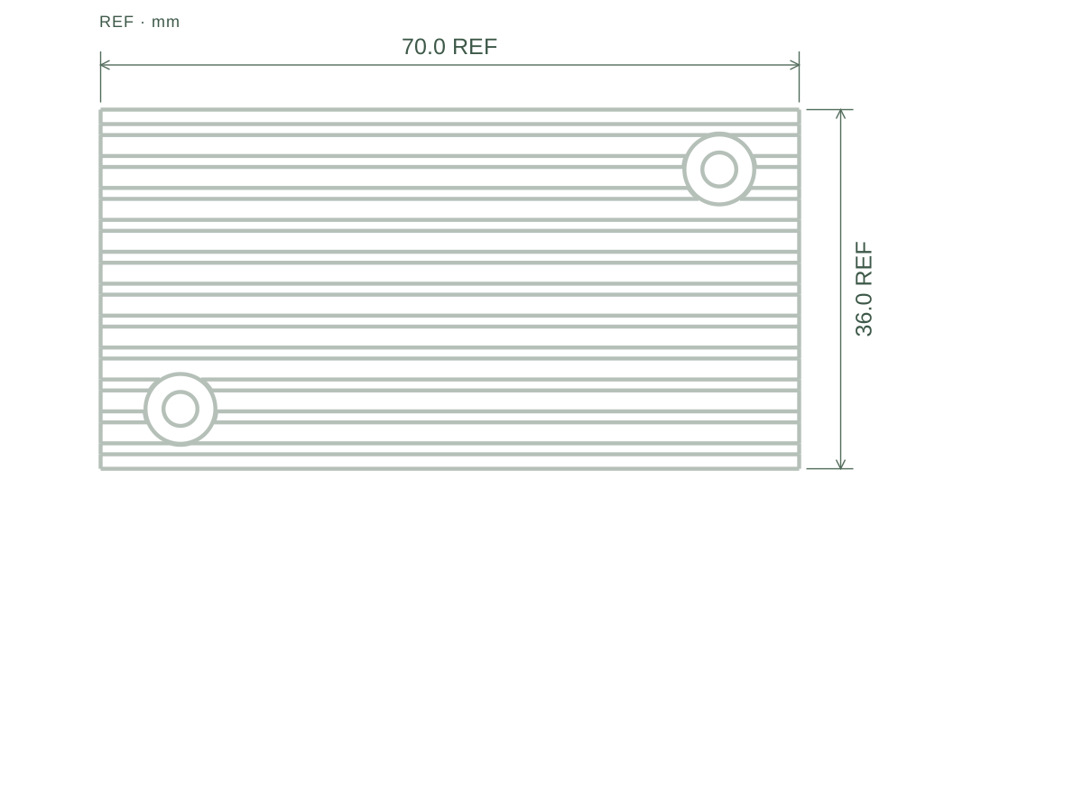

Make the mounting part of the thermal review.
A compact finned body shares limited space with fasteners and neighboring components. Review the contact footprint and mounting load alongside the available air path.
From production projects.
- Flatness on specified contact lands
- < 0.05mm
- Roughness on specified contact lands
- < 0.8μm Ra
- Specified aluminum alloy
- 6061
Selected contact-land limits from production-project drawings, not whole-part tolerances. Temper is not specified in these examples. Marked contact and mounting areas require a defined finish exclusion or post-machining route. These are drawing requirements, not measured results or a universal capability guarantee.
- Fins & clearance
- Define fin thickness, spacing and access for burr removal.
- Mounting features
- Check hole locations, fastener seats and the risk of distortion during assembly.
- Operating conditions
- Provide heat load, inlet temperature, airflow and interface material before evaluating thermal performance.
Similar purpose.
Different ways to make it.
Beyond the fins.
Consider the process.How the base and interfaces are made shapes what we can machine, join and inspect.
| Manufacturing route | Part construction | What we review with your drawing |
|---|---|---|
| Extruded profiles | A continuous aluminum section, cut to length. | Contact-face machining, mounting holes and cut ends. Confirm the available profile before adding custom features. |
| Skived fins | Thin fins raised from the same metal as the base. | Fin protection, remaining base thickness and accessible secondary machining. The fin-to-base connection is integral. |
| Assembled fin stacks | Separate fins joined to a base or heatpipe assembly. | Base geometry, locating features and joint allowances. Joining method and assembly responsibility need agreement. |
| Machined cold-plate parts | A body, cover and ports forming a coolant passage. | Channel access, seal lands, threads and cleanliness. Joining and leak acceptance belong to the assembled design. |
Our focus is precision metalwork and its inspection. Specialist fin forming, heatpipe manufacture, joining and complete cooling assemblies are scoped separately with the appropriate partners.
A better review starts at the interface.
Select a feature to see what should be defined before a thermal component moves into production.
Heat source → contact surface → heat-transfer structure
Make the contact condition explicit.
Specify the mating surface, datum scheme, flatness, roughness and interface material. Confirm whether acceptance applies before or after the final finish.
- Heat-source footprint and contact area
- Flatness and roughness on the controlled drawing
- Clamping pattern and inspection condition
A few details.
A better starting point.
Useful distinctions when turning a cooling concept into a component drawing.
More fins need enough flow.
Closer spacing adds surface area but can restrict the air passing through it. Fin pitch, channel length, available airflow and pressure drop should be considered together.
Bring the airflow direction and available envelope—not just a wattage target.
A heatpipe is not a water line.
A heatpipe is a sealed two-phase heat-transfer device. A pumped liquid loop instead moves coolant through a cold plate and radiator. Their interfaces and manufacturing routes are different.
Identify whether the drawing covers a base, a thermal subassembly or a fluid-carrying part.
Look at every wetted material.
For a liquid loop, review all metals in contact with the coolant, including fittings and the radiator. Mixed-metal compatibility and coolant chemistry matter alongside geometry.
Specify material, finish, sealing method and assembled test conditions together.
Further engineering reading
External technical references for the principles above; they do not describe XILILAI product qualifications.
THERMAL FIELD NOTES
The questions behind
the cooling hardware.
Market signals become useful when they lead to better drawings. Explore the decisions that connect server demand to air, liquid and manufacturing.

MANUFACTURING & VERIFICATION
From contact geometry to an agreed inspection record.
Functional dimensions
Contact faces, mounting datums, port locations and specified wall sections.
Edges & cleanliness
Accessible burr removal, channel cleanliness and handling requirements defined for the part.
Assembly acceptance
Leak integrity and thermal performance require agreed assembly-level tests; they are not inferred from a dimensional report.
Good questions.
Clearer decisions.
From a first drawing to a production order, start with the details that affect your part.
Ask about your applicationShape & process
What should I specify for a low-profile server heat sink?
Start with the usable space above the processor, the socket mounting pattern and the chassis air path. Include the board stack-up, fastener access and clearance to the cover. A server rack-height designation alone does not define the space available for the heat sink; the assembly drawing controls the envelope.
How do I choose between extruded, skived and stamped fins?
Extrusion suits a continuous cross-section that can be cut and machined. Skiving creates fins from the parent material, while stamped or folded fins are formed from sheet and may require a joining operation. Compare fin geometry, tooling, base contact and production quantity together. We review the machining scope and confirm specialist forming or joining separately.
What fin thickness and spacing can you manufacture?
Send the fin thickness, pitch, height, unsupported length and base thickness as separate dimensions. Pitch is the repeating distance between fins; the open air gap is a different dimension. Feasibility depends on the forming route, alloy, tool access and handling strength. A single minimum thickness would be misleading across extruded, skived and machined designs.
Precision & surfaces
What machining precision can XILILAI reference?
The 2025 register for the former Dongguan site lists accuracy entries of 0.01–0.02 mm for three-axis CNC, 0.02 mm for five-axis CNC and 0.005 mm for Swiss-type turning. These are historical equipment-register values, not current Shenzhen capability or a universal finished-part tolerance. We confirm the tolerance for each critical feature against its size, material, setup, treatment and agreed inspection method.
Is contact-face flatness the same as a dimensional tolerance?
No. A thickness tolerance controls a size; flatness controls the form of a surface. Specify the contact area, flatness, roughness and inspection condition separately, including whether the part is free or restrained. Thin bases can distort during machining, joining or clamping, so the acceptance condition matters as much as the numerical limit.
Should the thermal contact surface be anodized?
Define the finish by surface function. Mark any contact faces, threaded features and electrical bonding areas that need masking or a different treatment. State the coating specification and whether dimensions are accepted before or after finishing. A black surface alone is not evidence of a particular cooling performance.
How are dimensions and surface condition inspected?
The 2025 Dongguan metrology register included one CMM, three 2.5D instruments and three surface-roughness meters. Current Shenzhen instrument availability must be confirmed. For the project, agree the critical-characteristic list, datum scheme, accessible measurement points and report format. Instrument availability does not by itself establish measurement uncertainty for every feature.
Testing & ordering
Can you guarantee a wattage or thermal-resistance figure?
A dimensional drawing alone is not enough. Supply the heat-source footprint, power, temperature limit, interface material and mounting pressure, plus airflow or coolant conditions. Agree who validates the assembled thermal performance and under which test conditions. Thermal resistance must identify the measurement locations and operating conditions.
What do you need for cold-plate bodies and covers?
Provide the channel and cover drawings, seal lands, port details, joining method and wetted materials. For an assembled scope, specify the test medium, pressure, hold time and permitted leakage. Machining, joining, cleaning and leak testing must have clear responsibilities before production.
Can you support samples before a production order?
Share the sample quantity, forecast, drawing revision and target delivery date. We review stock, tooling and the manufacturing route before confirming quantity and timing. Agree first-article dimensions and any functional tests before releasing the production batch; sample approval should refer to the same revision and finish condition.
Specify the installed thermal interface.
The final contact condition connects the heat sink to the assembly. Add installation details to the part drawing so machining, finishing and verification refer to the same surfaces.
Prepare a server cooling hardware RFQWhat should accompany a heat-sink drawing?
Include the heat-source footprint, contact area, mounting pattern, available space and airflow direction. If thermal performance is part of the enquiry, also define heat load, ambient conditions, interface material and the validation method.
Which surfaces need separate finish instructions?
Identify thermal contact faces, threaded holes and grounding areas. Specify masking, surface texture and any dimensions that apply after finishing; an appearance finish is not a complete thermal-interface specification.
A CLEAR START
Bring us the interface. We’ll discuss the manufacturing route.
Share the design intent, the critical features and the scope you need. We’ll review the details before confirming the route and quotation.
Send a component for review.
- 3D model + controlled 2D drawing
- Material, finish and critical surfaces
- Cooling context, sealing scope and inspection
- Quantity, target timing and delivery region