

Optical Module Hardware
Precision metalwork.For optical supply chains.
Housings, covers and locating parts for optical-module programmes. CNC machining and partner processes, developed around the interfaces your assembly needs.
Discuss your componentDifferent buyers. Different component responsibilities.
We focus on the mechanical supply chain around optical transceivers. The first commercial question is who owns the component drawing and who approves the mating interface. That determines the quotation, sample package and qualification route.
Optical-module manufacturers
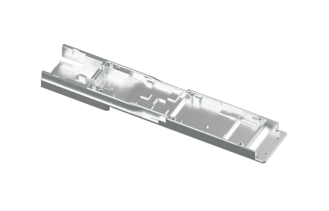
Housing bodies, covers, locating parts and release hardware. Review internal seats, board supports, cover closure and the finished assembly envelope.
Cage & connector suppliers
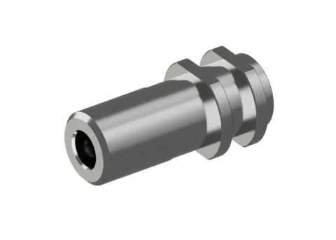
Formed shields, grounding contacts and retention components. Review spring material, burr direction, contact geometry and compatibility with the mating module.
System & thermal integrators
Heat-contact bases, supports and mounting hardware. Review module-to-host stack-up, preload, airflow clearance and who signs off thermal performance.
Where optical-network growth
reaches the metal supply chain.
Higher link speeds create engineering programmes, but do not automatically increase the value of every metal part. The addressable opportunity depends on the package, its cooling arrangement, the customer's make-or-buy decision and the cost of qualifying another source.
800G and 1.6T pluggable modules
OSFP supports both rates. A bandwidth upgrade can retain an external envelope while changing internal seats, heat-contact geometry or assembly clearance. A form-factor name is therefore a starting point for review, not a production drawing.
Entry point: development housings, revised lids and drawing-defined locating parts. Compare CNC sampling with a production blank route once geometry and demand stabilise.
Module cooling and host hardware
Integrated and riding heat sinks put different interfaces on the module and host. The module body, cage and heat sink may be purchased by different organisations; the thermal contact belongs to the assembled stack.
Entry point: contact lands, heat-spreader bases and mounting hardware. Agree the mating parts and contact load before assigning flatness or finished-height acceptance.
Second-source and cost-down programmes
An existing drawing can still carry process assumptions from the incumbent supplier. Changing the alloy, blank, fixture or finish can change distortion, coating build-up and fit.
Entry point: a controlled comparison of samples, finished dimensions and process risks. Cost-down should include tooling, secondary operations, yield and inspection, rather than machining price alone.
CPO and external laser packaging
Co-packaged optics changes where optical functions sit in a system. OIF publishes separate agreements for co-packaged modules and external laser pluggables. These are distinct packaging programmes, not a direct extension of a conventional transceiver shell.
Development scope: customer-defined supports, covers and thermal interfaces. Review optical keep-outs, contamination limits and assembly ownership before committing to parts or tooling.
From optical requirements to precision metal components.
Why we are building
in this supply chain.
Our starting point is precision metalwork: machined datums, thin sections, small turned features and dimensions that must remain correct after finishing. Optical-module hardware brings these disciplines into a compact assembly where a small change can affect fit, contact or serviceability.
We are directing our work towards housings, covers, thermal-contact parts and locating hardware that can be reviewed against controlled drawings. The aim is to connect machining with the required blank, forming and finishing processes, while keeping each supplier's responsibility traceable.
CNC machining capability Small turned components Inspection equipment interfaces- Direct manufacturing scope
- CNC milling, turning and dimensional inspection, subject to review of part size, material, geometry and acceptance requirements. Existing machining capability is the starting point; it does not by itself establish optical-programme qualification.
- Partner-supported scope
- Cast blanks, stamped or drawn shells, formed spring contacts and specialist finishes. Route, supplier, tooling and inspection hand-offs are confirmed for each project.
- Customer / system-owner scope
- Optical design, electronics, active alignment and module-level thermal, EMI and reliability approval. Acceptance of a metal component is separate from qualification of the transceiver.
Precision Metal Components For Optical Communications
Geometry. Interfaces. One BOM.
Open and close the production housing pair to explore its geometry. Review the drawing requirements for inspection after fastening, alongside each part’s mating features and finished-surface requirements.
Compare receptacle parts and completed metal-component projects, including precision sleeves, a tail seat and optical-package metalwork, in one BOM review.

Drag to rotate · Scroll or pinch to zoom
CAD geometry from the production project. Body and lid only; fastening hardware and internal components are not shown.
Two production parts.
One drawing-defined fit.
XILILAI has manufactured this housing and lid pair in volume. Explore the supplied component geometry, then review the dimensions that matter when the two parts come together.
- Specified material
- AL6063
- Finish system
- Copper + nickel
Measure the pair after fastening.
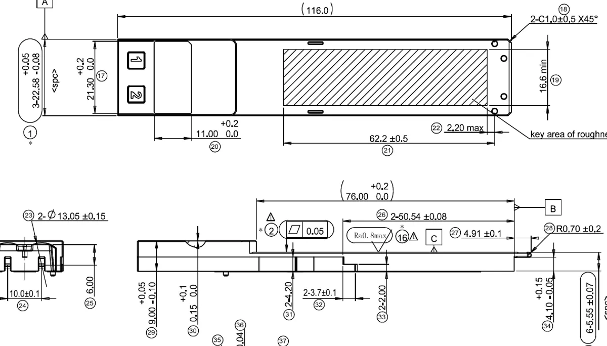
The drawings require assembly checks at the front, middle and rear with the mating part fastened. Separate part reports alone do not complete this check.
- Assembled thickness
- 9.45 ± 0.10 mm
- Assembled width
- 22.58 ± 0.08 mm
Keep each surface requirement local.
Body flatness: 0.05 mm. Lid flatness: 0.10 mm. Both have designated Ra 0.8 μm areas and defined plating-thickness test points.
Values are requirements for this drawing pair, not measured lot results or general machining tolerances. CAD motion shows component alignment, not a fastening or optical-performance test.
Review a housing and lid programme →Read the plating and assembly tolerance study →The finish belongs in the dimensional review.
Both drawings specify a copper underlayer of 12–25 μm and a nickel top layer of 3.5–8 μm. Review the coating stack with the finishing supplier alongside screw features, contact zones and mating clearances.
Bring the complete acceptance package.
Supply both part revisions, material condition, marked critical dimensions, surface requirements and the mating assembly. Agree the inspection method, coating records and sample approval before production.
Prepare an optical housing RFQ →Where receptacle metal parts are used.
At the optical port, a receptacle provides the mechanical interface between a fibre connector and the optical subassembly. Metal housings and bases locate and retain the associated parts; the complete receptacle design determines the arrangement of the fibre stub, sleeve and other optical elements.
For an RX assembly, review the receptacle interface with the receiving optical path. The metal parts alone do not establish optical alignment, insertion loss or receiver performance.
Application references: Orbray receptacles · General Optics fibre-stub assemblies.
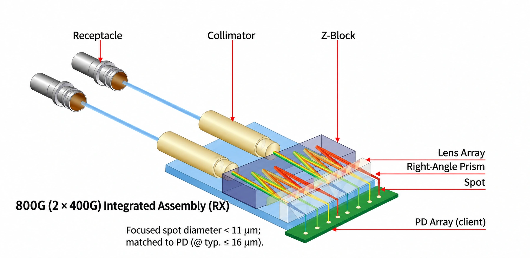
English redraw of the supplied HYC reference illustration. Optical values belong to that reference, not XILILAI test results. View full-size diagram ↗
Review the evidence. Prepare your requirements.
These are reference component drawing requirements, not measured results or a factory-wide tolerance promise.
- Specified material: 6063Prepare an editable RFQ →
- Local flatness: 0.05 mmPrepare an editable RFQ →
- Copper underlayer: 12–25 μmPrepare an editable RFQ →
- Nickel top layer: 3.5–8 μmPrepare an editable RFQ →
Applies only to the cited component and marked feature. Confirm the controlled drawing revision and acceptance method. Drawing revision: not supplied Measured result: not supplied
Public source →- In-house machining review
- CNC milling, turning and dimensional inspection are reviewed against the actual part.
- Partner scope to agree
- Confirm forming, welding, finishing and specialist test responsibilities per project.
- Customer / system owner
- Confirm the applicable module specification and who validates assembly fit, thermal behaviour and optical performance.
Information to confirm
- Controlled drawing and model revisionsRequired
- Material, condition and quantityRequired
- Inspection method, records and sample approvalRecommended
- Separate body / lid revisions and fastening arrangementRequired
- Critical contact areas and mating clearancesRequired
- Coating thickness, masking and inspection after platingRequired
- Cleaning and packagingRequired
- Applicable module specification / revision and system validation ownerTo confirm
Not supplied; confirm for this project.
Prepare an editable RFQ →A housing is only
part of the package.
The opportunity extends from machined bodies to formed contacts and small mating parts. Each item needs its own drawing, manufacturing route and acceptance criteria.
These are component families for project review. Tooling, specialist operations and assembly scope are confirmed before quotation.

Housing & cover
Internal seats locate the board and optical subassemblies. Cover joints, cage clearances and thermal contact lands must be related to the same datums.
CNC from solid for development; cast blanks with secondary machining where geometry and volume justify tooling.
Shielding & grounding contacts
Formed spring contacts bridge metal interfaces. Burr direction, free height, deflection and the specified surface treatment affect the assembled contact.
Precision stamping and forming; material condition and finishing agreed with the specialist supplier.
Retention & release hardware
Pull features, sliders and return elements need defined travel and clearance. A dimensional check does not establish release force or cycle life.
Small machined or formed parts, with sample fit and functional testing against the customer’s mating assembly.
Port surrounds & locating parts
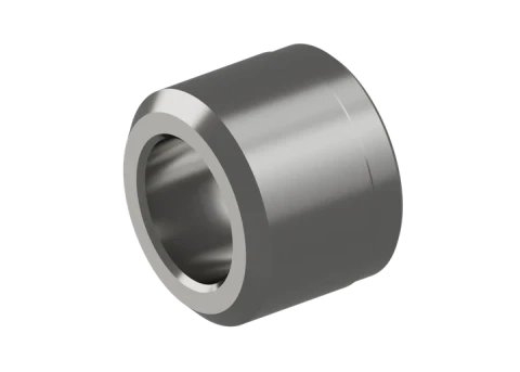
A thin-wall shield sleeve and a precision locating sleeve serve different functions. Identify shielding, guidance or optical positioning before choosing a process.
Deep drawing or stamping for suitable thin shells; turning for drawing-defined bores and shoulders.
Precision along the optical axis.
Beyond transceiver housings: metal barrels and guide components for optical positioning assemblies. Explore the interfaces that deserve their own manufacturing review.
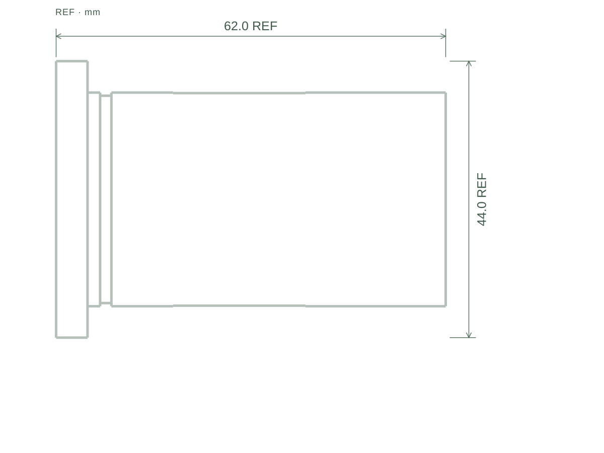

A common axis. Several critical surfaces.
A stepped bore, locating diameter and retaining thread have different jobs. Review their datum relationships, wall support and finished condition together.
From production projects.
- Selected coaxiality / perpendicularity callouts
- 0.02mm
- Selected bore and shaft fit classes
- H8 · g6
- Specified barrel / guide materials
- 2A12-T6 / 304
Selected requirements from production-project drawings. Fit classes refer to different features, not a verified mating pair. Final dimensions and geometric tolerances are specified after treatment. These are drawing requirements, not measured results or a universal capability guarantee.
- Locating surfaces
- Define the fit and relationship between the lens seat, outside diameter and shoulder.
- Threads & reliefs
- Review thread class, tool access, edge condition and clearance for the mating part.
- Finished inspection
- Agree coating allowance and the features to measure after surface treatment.
One coordinated supply.
Across the metal parts list.
XILILAI brings together in-house manufacturing and an established supply network for precision metal components used in optical communications. Coordinate stamped transceiver housings, optoelectronic packaging parts, precision receptacle parts, heat sink fins and retention clips through one BOM review, with the manufacturing route and acceptance requirements agreed for each item.
The aluminium housing models above provide an additional interface and geometry reference. They are separate from the stamped-housing production scope.
Explore the housing in 3DProduction housings, formed covers and stamped retention features.
Review production parts alongside the drawing revision, sheet thickness, bends, formed tabs and mating interfaces. Define checks for burrs, springback, critical dimensions and surface condition, with the agreed inspection records supporting batch release.
The aluminium housing models above provide an additional interface and geometry reference. They are separate from the stamped-housing production scope.
Explore the housing in 3DFrames, seal rings, lids, baseplates and feedthrough tubes.
Match the material, sealing faces and plating system to the joining route. Agree the responsibilities and acceptance criteria for brazing, sealing and leak testing when these are included in the package.
Precision sleeves, mounting bases, flanges and front housings.
Review precision-turned bores, locating shoulders, flange faces and small chamfers together with the mating parts. Agree the datum relationships, material, surface roughness and finished dimensions after any specified surface treatment.
Individual fins, interlocking fin assemblies, folded fin assemblies and retention clips.
Compare fin thickness, pitch, interlocking or folded construction and the attachment to the heat-spreader base. Review clip engagement, contact pressure and assembly access together with the available envelope and airflow.
Precision belongs where the assembly needs it.
Select a feature to explore the mechanical requirements that support a clear manufacturing review.
Contact surfaces and locating features belong in the same review.
Locate the functional features first.
Start with the features that locate the assembly. Relate bores, shoulders and mounting faces to a coherent datum system, so inspection answers the same question as assembly.
- Mating model and datum references
- Fit, position and concentricity requirements
- Accessible inspection features
Thin walls. Small edges.
Measured surfaces.
Match each critical feature to a machining decision and an inspection record. These are the review points for your component, from the first sample to repeat orders.
Thin walls
Review wall height and thickness together with ribs, clamping access and the order of material removal. Plan support around the functional datums, then check the surfaces that can move after unclamping or finishing.
What to verify
Record wall thickness and local flatness with the inspection support condition identified.
Review thin-wall geometrySmall chamfers
Mark the edges that guide assembly or protect a mating surface. Keep specified chamfer sizes and angles separate from general edge breaking; review small-tool access and how deburring or coating could change the profile.
What to verify
Use a suitable inspection view for size and angle; check burrs and edge damage separately.
Define the edge conditionSurface roughness
The reference drawings specify local Ra 0.8 μm requirements. Link each callout to its marked contact surface and confirm whether acceptance applies before or after coating. Review roughness and flatness as separate characteristics.
What to verify
Identify the measurement location, direction, evaluation settings and drawing revision in the agreed inspection record.
Specify surface measurementMaterial and finish are part of the fit.
Housing materials
Confirm the specified alloy and condition against thin-wall geometry, thermal contact, weight and the chosen production route.
Turned interfaces
Choose sleeve and locating-part materials from the mating system requirements. Review fit, wear, finish and mixed-material contact together.
Surface treatment
Define coating thickness, masking, grounding contacts and visible areas. Do not let an appearance callout substitute for a functional finish specification.
CNC milling supports pockets, contact faces and mounting features; turning supports bores, sleeves and shoulders. Where a casting or stamped blank is proposed, confirm tooling, secondary machining and partner responsibilities before release.
Explore our machining capabilitiesConnect the processes.
Keep the interfaces controlled.
A module maker, a cage supplier and a thermal integrator may own different drawings in the same assembly. Establish the purchasing boundary and mating-part owner before combining the work into one RFQ.
Material & blank
Alloy, temper, stock or casting route. Confirm tooling ownership and which surfaces retain machining allowance.
Machining & forming
Machine the functional datums; control formed contact geometry. Agree the hand-off dimensions between operations.
Finish & inspection
Specify coating, masking and edge condition. Inspect critical fits in the finished state required by the drawing.
Fit & release
Check the agreed mating samples. Record drawing revision, inspection results and any assembly-level tests still required.
XILILAI’s role centres on precision machining and dimensional inspection. Casting, stamping, deep drawing, spring forming and specialist finishes are evaluated with partners for the individual project. Thermal, EMI and optical performance require separately agreed assembly validation.
Explore our manufacturing networkThe right equipment.
For the feature being checked.
Our equipment records include five-axis machining, coordinate and vision measurement, and surface roughness instruments. The part geometry and acceptance method determine which equipment belongs in your inspection plan.
- Five-axis machining · access & setups
- Review angled faces, tool reach and datum transfers. Multi-face access can reduce repositioning; thin-wall support and the cutting sequence still need their own review.
- Vision measurement · small edges
- Choose the view and resolution for the specified chamfer or profile. Microscopy helps examine burrs and surface damage; a visual check does not replace dimensional measurement.
- Coordinate measurement · datums & form
- Match probing access and part support to locating faces, hole positions and local flatness. Agree how thin sections are supported during inspection.
- Roughness instruments · surface profile
- Confirm probe access, trace direction and evaluation settings on the specified surface. For a narrow contact land, agree a suitable method before committing to a result.
Factory footage shows process and inspection context. For your part, agree the instrument, calibration status, marked features and required records at first-article review.
Before we
make the part.

Are the two 3D parts complete optical modules?
They are a housing body and a housing lid. The supplied drawings identify mechanical components, not complete transceivers. Module speed, optical performance and compliance with a particular form factor cannot be established from these parts alone.
Why do the body and lid have different flatness requirements?
Their drawings control different surfaces: the body has a local 0.05 mm flatness callout and the lid has a 0.10 mm callout. Keep the measurement area, support condition and inspection method linked to each drawing. A local tolerance should not be applied to every surface or quoted as a general machining capability.
How should the copper and nickel coating stack be reviewed?
These drawings specify a 12–25 micrometre copper underlayer and a 3.5–8 micrometre nickel top layer. Review coating thickness and distribution with the finishing supplier, especially around small threads, screw seats and mating surfaces. Confirm which dimensions are accepted after finishing and what records are required.
Does a reliability requirement on a drawing mean testing has passed?
No. A required test duration, capability index or restricted-substance requirement is an acceptance input. Evidence of conformity requires the agreed test method, traceable samples and an actual report for the relevant revision and production route.
Does every optical module need a separate heat sink?
No. The cooling arrangement depends on module power, package, airflow and host design. Standard OSFP integrates a heat sink; OSFP-RHS requires a separate riding heat sink. Confirm the applicable mechanical specification and thermal-contact design, including whether an interface material is required.
Can you work from a module form-factor name alone?
A form-factor name helps describe context, but it does not replace a controlled mechanical drawing. Share the mating geometry, critical dimensions, finish and the applicable specification revision.
Do you manufacture complete optical transceivers?
This page covers precision metal hardware. Electronic assembly, optical alignment and transceiver qualification are separate scopes that must be explicitly agreed.
How should thermal and electrical contact areas be specified?
Mark the functional contact zones, finish and masking requirements on the drawing. Include the mating assembly and define whether dimensions and acceptance apply before or after coating.
How are thin walls inspected without changing their shape?
Agree the support and clamping condition before measurement. Select contact or non-contact methods to suit the feature and its stiffness; check which dimensions must be accepted after unclamping or finishing. The inspection record should identify this condition.
Is edge breaking the same as a specified chamfer?
No. General edge breaking removes sharpness; a dimensioned chamfer has a defined size or angle. Identify the controlled edges and inspection view, and review whether deburring and coating could change the accepted profile.
How is roughness verified on a narrow contact surface?
First confirm that the specified surface offers enough access and trace length for the agreed method. Record the parameter, units, direction, evaluation settings and inspection stage. If a stylus cannot reach the surface, agree an alternative with the design owner; appearance alone cannot establish the Ra value.
What a sourcing team
needs before production release.
For programmes in China and overseas, the useful evidence is tied to a part revision and a production route. Sample appearance, machine count and a general tolerance claim cannot establish repeatability.
Drawing review & quotation
Identify critical-to-quality features, datum scheme, inspection access and finished-state dimensions. Separate one-off tooling and fixtures from recurring part cost; state material, finishing and packaging assumptions.
Review recordMarked drawing, open technical questions, proposed process route and agreed acceptance plan.
First articles & assembly trial
Measure the agreed features after treatment. Check lid closure, cage entry, latch travel and contact surfaces with customer-approved mating parts. Record discrepancies before changing either geometry or process.
Sample evidenceRevision-linked dimensional report, material / finish records as agreed, and customer feedback from the assembly trial.
Pilot run & repeat orders
Confirm the intended production route and inspect variation across the agreed sample plan. If capability indices are required, agree the measurement system and data quantity first. Control changes to blank source, tooling and finishing.
Release basisApproved sample, agreed control plan, lot identification and a documented change-notification process.
Programme-specific requirements may include RoHS / REACH declarations, material traceability, cleanliness limits and packaging controls. Confirm the required documents and test methods at quotation; they are not implied certifications of every proposed part.
Before the first sample.
Send the interfaces along with the individual part drawing.
Read the optical hardware sourcing guide- Package & mating parts
- Form factor and revision, cage or connector model, keep-out zones, assembly datums and mating samples where available.
- Contacts & moving parts
- Thermal and grounding zones, coating exclusions, latch travel, required operating forces and the agreed cycle-test method.
- Acceptance & ownership
- Finished-part tolerances, inspection records, sample quantities and who validates thermal performance, EMI and optical alignment.
Define which side of the connection.
The module enclosure, host cage and heat sink are different components. Name the required item and interface revision before specifying its material or manufacturing route.
Prepare an optical-module housing RFQIs a module housing the same as a host cage?
No. The housing encloses the module; the cage positions it on the host side and may incorporate separate retention, shielding and thermal features. State which item is being sourced and provide the applicable mating drawings.
How should a pluggable-module interface be specified?
Provide the form factor, applicable mechanical specification and revision, mating envelope, latch clearances and thermal contact requirements. A form-factor name alone does not define every feature or establish compliance.
Does a metal enclosure establish optical or EMI performance?
No. Enclosure geometry and contact surfaces support the assembly, but optical, electrical, EMI and thermal performance require the relevant system validation. Separate component inspection from these tests.
One BOM.
An agreed delivery scope.
Share the component drawings together with a revision-controlled bill of materials. Identify the quantity of each part per set, the required finished condition and any mating parts supplied by another manufacturer.
We will review the package before confirming the manufacturing scope and quotation.
Prepare a multi-part enquiryStart an editable project draft. Saving a draft does not submit an enquiry.
- Part control
- Part numbers, drawing revisions, materials, finishes and quantities per set. Identify which items need to arrive together.
- Interface control
- Mating features, datum relationships, assembly sequence and finished-state dimensions. Include the relevant interface drawings.
- Delivery scope
- Separate parts, quantity-matched kits or agreed mechanical preassembly. Define the included operations and who accepts the assembled result.
- Release records
- Agreed dimensional inspection, material and finish records, part identification and traceability. Confirm any specialist testing before quotation.
A CLEAR START
Review a part. Define the production route.
Share the design intent, the critical features and the scope you need. We’ll review the details before confirming the route and quotation.
Send a component for review.
- 3D model + controlled 2D drawing
- Mating parts, datums and critical fits
- Material, coating and contact zones
- Quantity, inspection and target timing